Lesson 5: Understanding Line Following and Sensor Positioning
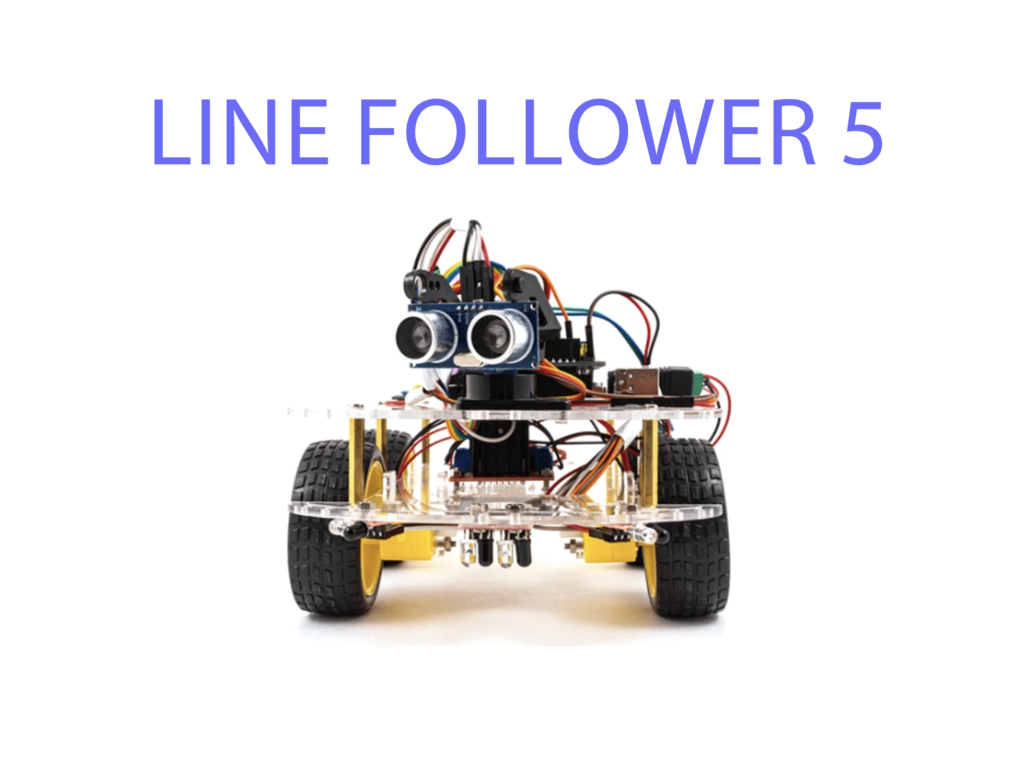
Components:
- 2x IR sensors (left and right)
- 2x DC motors
- 1x L298N H-Bridge motor driver
- 1x ESP32
- Jumper wires
Code:
This lesson focuses on placing the sensors correctly and adjusting motor behavior based on the sensor readings. Here’s a basic concept to start reading both sensors.
from machine import Pin, ADC
import time

# Define sensor inputs
left_sensor = ADC(Pin(34))  # Replace with actual GPIO
right_sensor = ADC(Pin(35))  # Replace with actual GPIO
left_sensor.atten(ADC.ATTN_11DB)
right_sensor.atten(ADC.ATTN_11DB)

while True:
    left_value = left_sensor.read()
    right_value = right_sensor.read()

    print("Left Sensor:", left_value, "Right Sensor:", right_value)
    time.sleep(0.5)
Explanation:
- Students can use this code to see the difference between the left and right sensors and determine the best placement.


